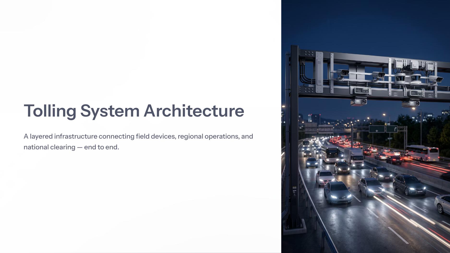
End-to-End Tolling Architecture
A layered animation connecting roadside sensing, edge processing, regional operations, national clearing, settlement and analytics.
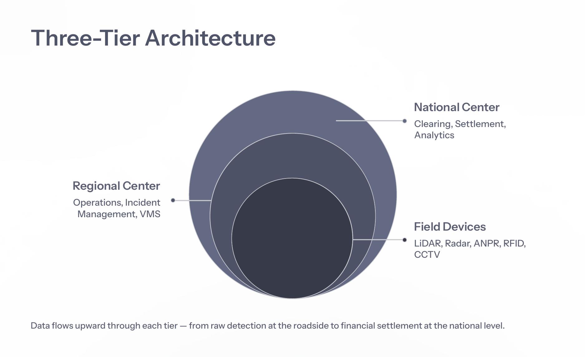
A layered MLFF architecture connecting roadside detection, regional operations, command centers, clearing, settlement and analytics.
A layered animation connecting roadside sensing, edge processing, regional operations, national clearing, settlement and analytics.
A layered animation connecting roadside sensing, edge processing, regional operations, national clearing, settlement and analytics.
Each sensor has a distinct purpose: classification, speed, identity, transponder read and enforcement evidence.
Vehicle classification, length profiling, height and point-cloud geometry.
Open →Speed detection, gap measurement, target tracking and lane continuity.
Open →Automatic number plate reading for identity and enforcement workflows.
Open →On-board unit or FASTag transponder reads and account linkage.
Open →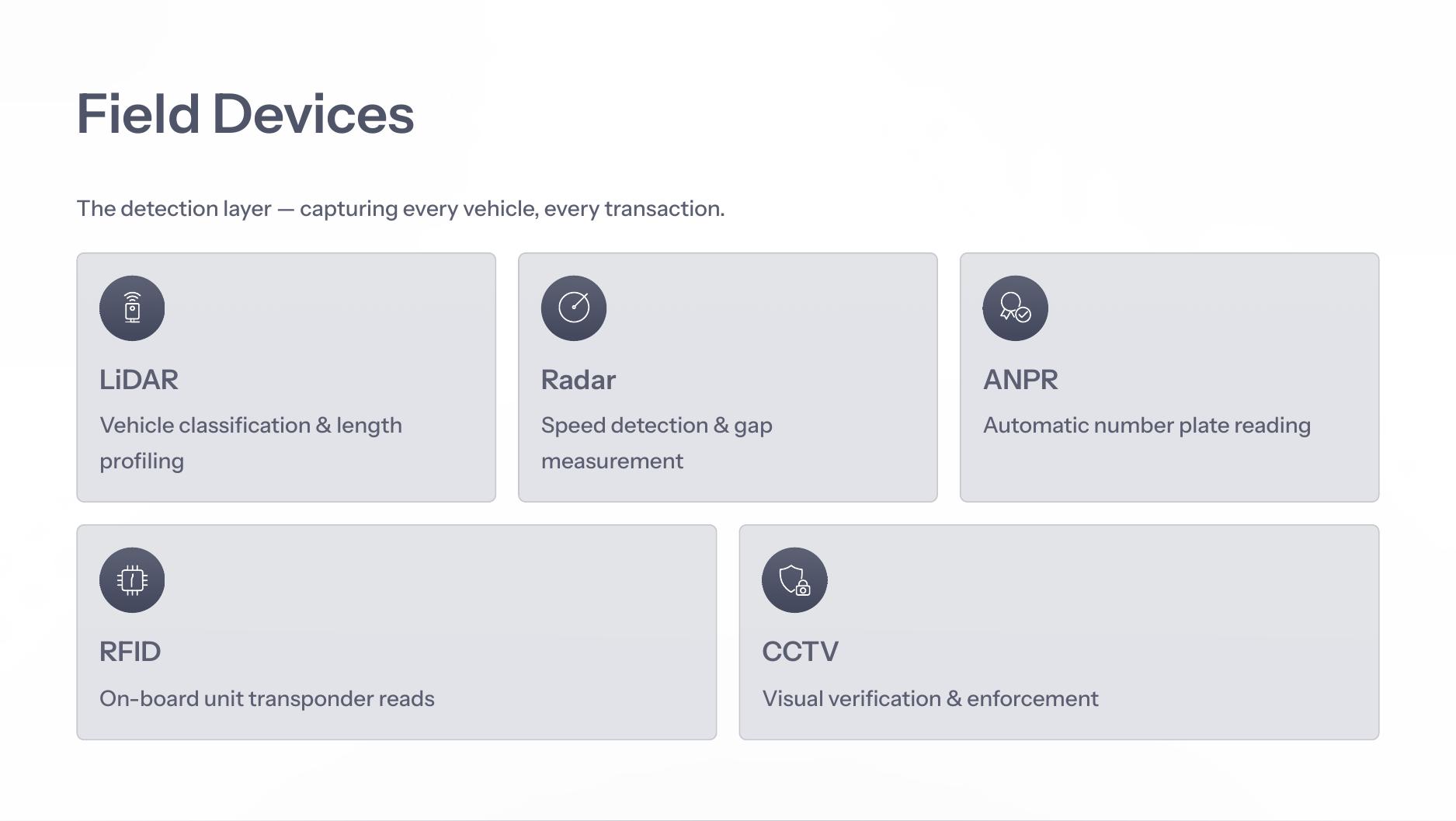
Raw detection starts at the roadside. Regional centers process transactions and incidents. National systems aggregate clearing, settlement and analytics.
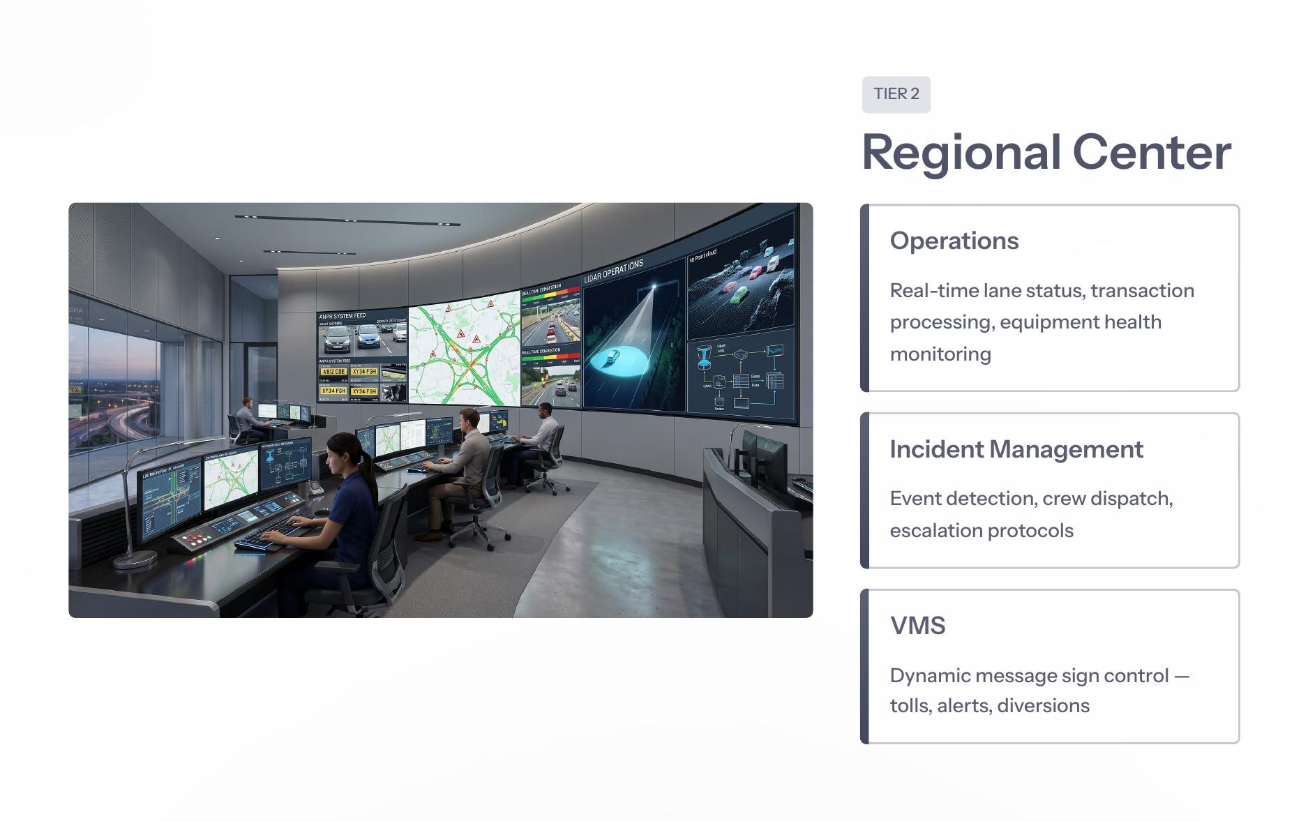
The regional layer manages real-time lane status, transaction processing, equipment health, event detection, crew dispatch and dynamic message signs.
Lane status, transaction processing and equipment health monitoring.
Detection, classification, crew dispatch and escalation protocols.
Dynamic sign control for tolls, alerts, diversions and safety messages.
Fault visibility and coordinated maintenance dispatch.
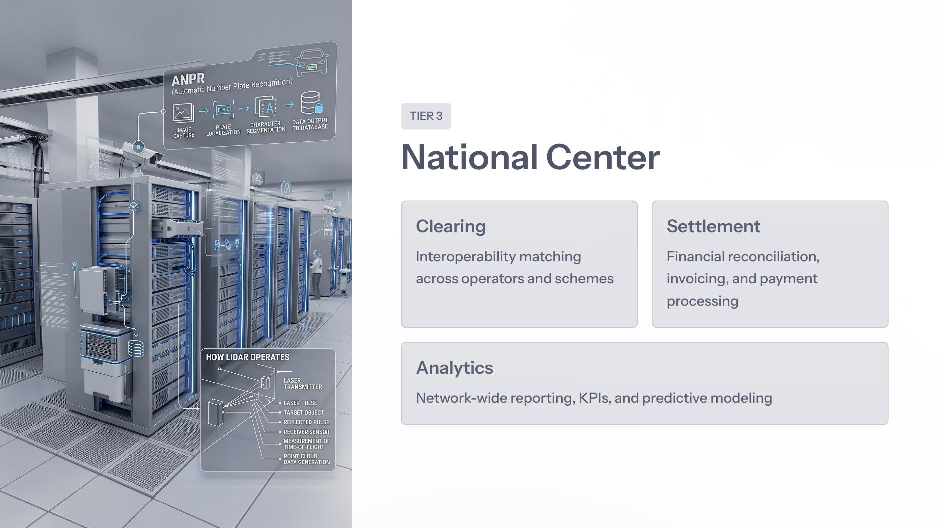
The national layer is responsible for interoperability matching, financial reconciliation, invoicing, payment processing, KPIs and predictive modeling.
Interoperability matching across operators and schemes.
Financial reconciliation, invoicing and payment processing.
Network-wide reporting, KPIs and predictive modeling.
Regulatory data products and audit-ready reports.
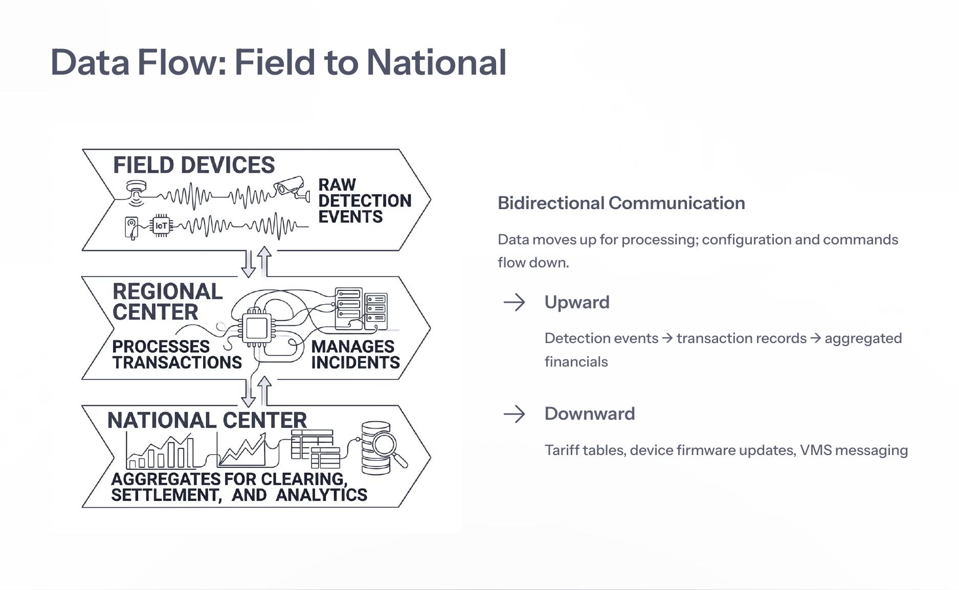
Upward communication moves from detection events to transaction records and aggregated financials. Downward communication carries tariff tables, device firmware updates and VMS messaging.
LiDAR and radar provide lane-accurate classification, speed and geometry. ANPR and RFID provide identity capture. CCTV supplies timestamped enforcement evidence for dispute resolution.
View Sensor Fusion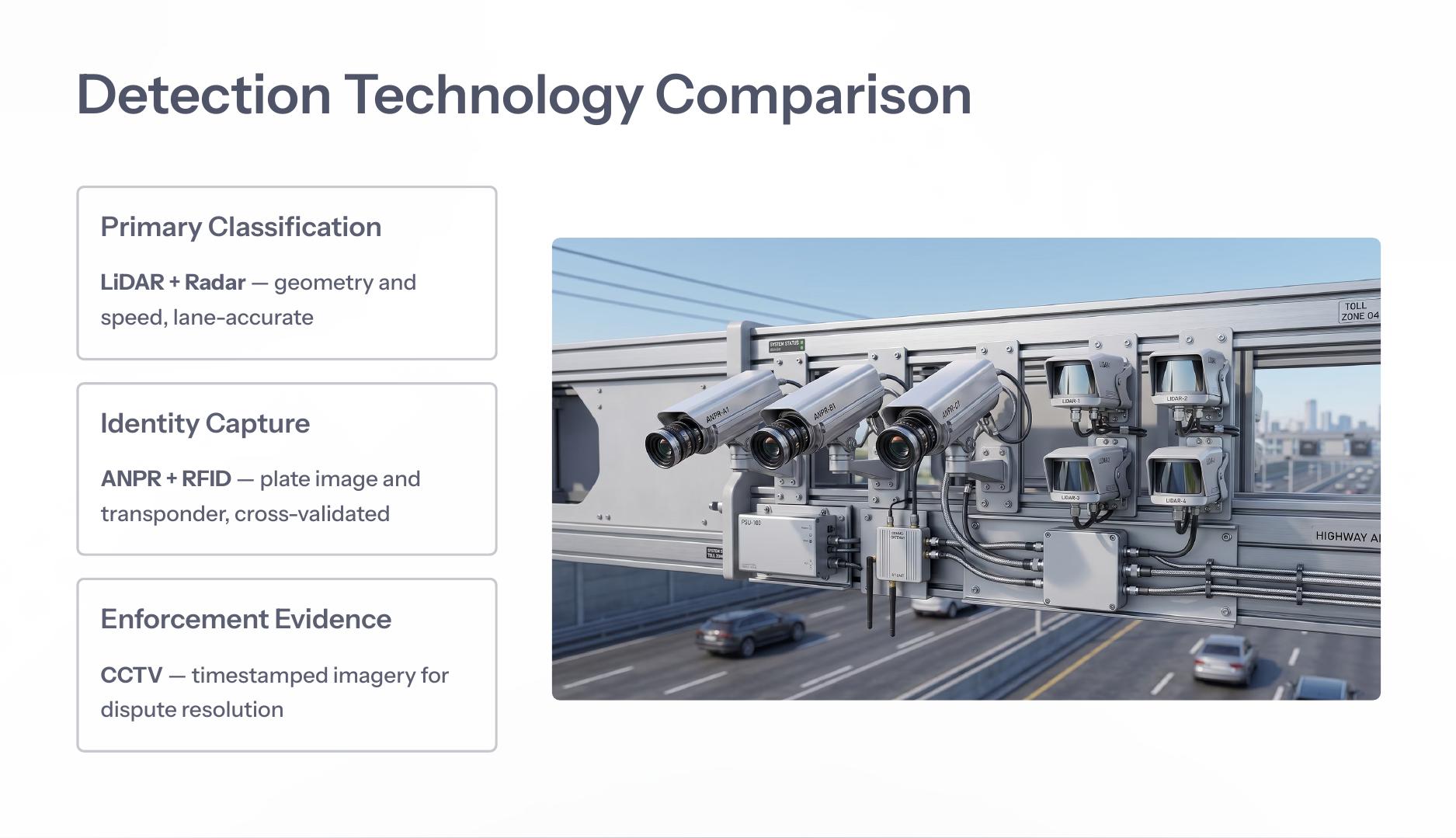
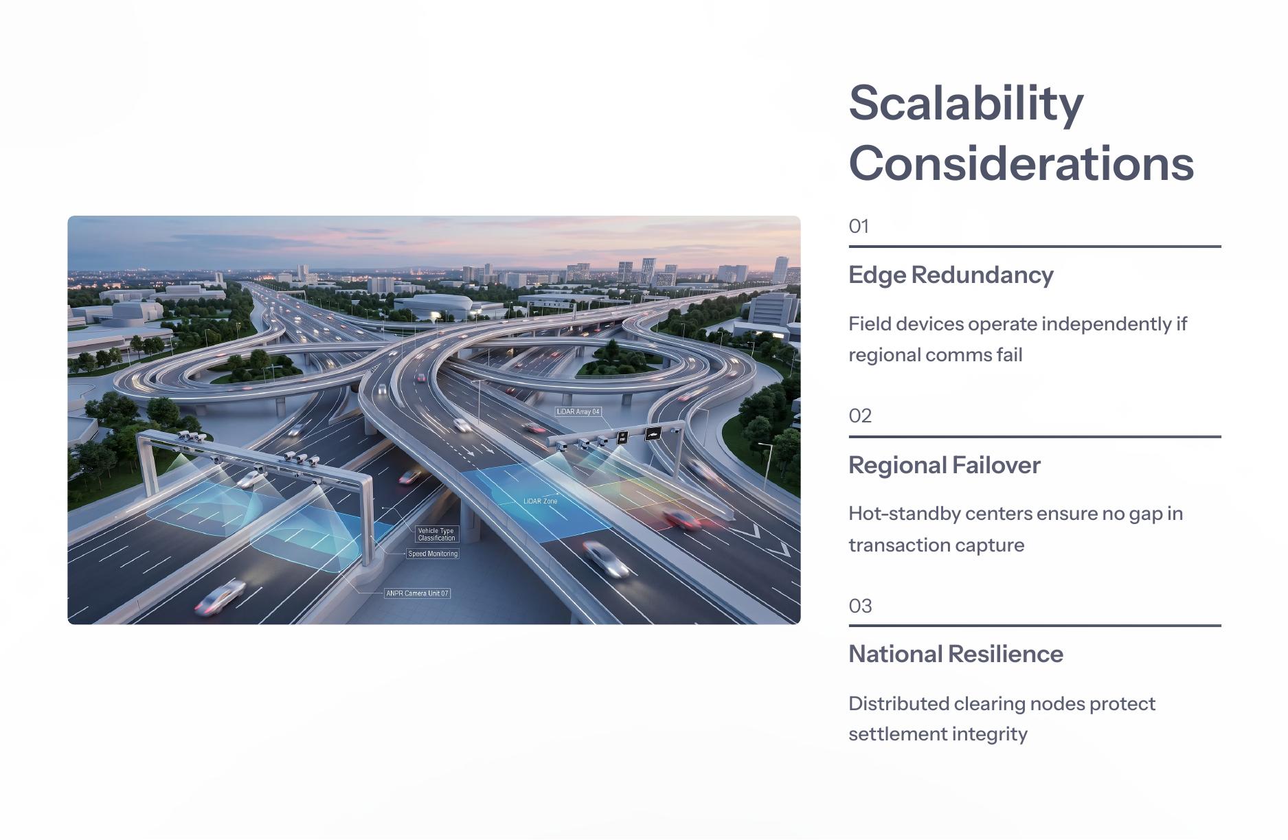
Field devices operate independently during regional communication failure. Hot-standby regional centers prevent transaction gaps. Distributed national clearing nodes protect settlement integrity.